Nikunj Patel
at
Nikunj Patel
at

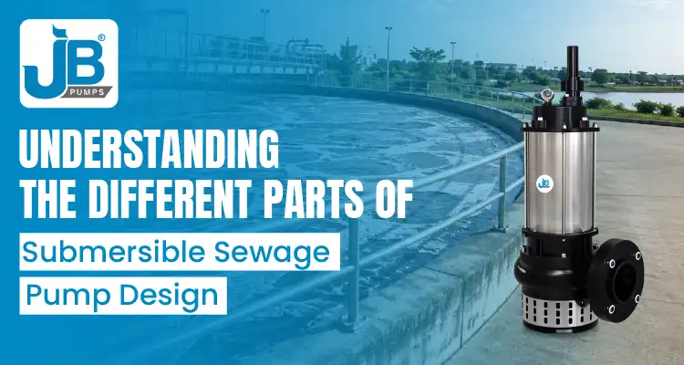
A submersible sewage pump is built from a coordinated set of hydraulic, mechanical, sealing, and electrical components designed to operate while the complete pump and motor assembly is submerged in wastewater. This guide explains the major parts, from the impeller and volute casing to the motor protection system, so you can read a pump specification sheet with more confidence and evaluate whether a design suits the actual application.
The article also explains how these components work together and which details deserve attention before purchase. Where a specification varies by model or manufacturer, the safest approach is to confirm the current technical datasheet rather than rely on a general industry rule.
Key Takeaways
- Sealing Matters: Submersible sewage pumps commonly use a double mechanical seal arrangement because the motor must remain isolated from the pumped wastewater.
- Check Protection Ratings: Verify the stated IP rating and motor insulation class and confirm the manufacturer’s permitted immersion and operating conditions.
- Materials Must Match the Fluid: Cast iron is common for general sewage duty, while stainless-steel options may be considered where corrosion is a concern.
- Impeller Geometry Is Application-Specific: Non-clog, semi-open, channel, and vortex designs handle solids differently, so selection should reflect the actual debris and fiber profile.
- Shaft and Bearing Design Affect Reliability: Shaft alignment, bearing arrangement, and surface condition influence vibration, seal life, and rotating-element stability.
- Starting Method Is Not Determined by One kW Threshold: DoL, Star-Delta, soft starters, and variable-speed drives are selected according to motor design, supply limitations, starting torque, and control requirements.
- Thermal and Level Protection Serve Different Functions: Motor overload or temperature protection safeguards the electrical side, while float switches or level sensors can help prevent operation below an acceptable liquid level.
- Seal-Chamber Inspection Can Support Maintenance: Where the pump design includes an oil-filled seal chamber, checking the oil condition can help identify seal deterioration before liquid reaches the motor cavity.
Submersible Sewage Pump Parts: Quick Reference
Here is the main parts list at a glance before we go component by component. The current JB Pumps product information and material-of-construction tables are available on the Submersible Sewage Pumps page.
- Volute casing: contains the impeller and directs flow toward the discharge.
- Non-clog, semi-open, channel, or vortex impeller: transfers energy to the wastewater while providing the required solids passage.
- Suction components and wear surfaces: protect or guide the inlet area where the specific pump design includes replaceable wear parts.
- Shaft: transmits motor torque to the impeller and passes through the bearing and sealing arrangement.
- Submersible motor: drives the pump while enclosed in a housing designed for submerged operation.
- Double mechanical seal: separates the wet end from the motor side and limits liquid ingress along the shaft.
- Bearings: support the rotating shaft and carry radial and axial loads generated by the motor and hydraulic system.
- Power cable and cable entry: provide electrical supply while maintaining the integrity of the submerged enclosure.
- Thermal or overload protection: protects the motor when temperature or electrical loading exceeds the intended operating condition.
- Level-control protection: may use a float switch or level sensor in the control system to prevent operation at an unsuitable liquid level.
- Motor starter or control system: manages motor starting and protection according to the motor and site electrical design.
What “Submersible Sewage Pump Design” Actually Means
A submersible pump differs from a surface-mounted or dry-installed pump because the motor and hydraulic end operate as a submerged assembly inside the wet well, sump, or wastewater source. That design choice affects almost every component:
- The motor enclosure and cable entry must resist liquid ingress under the manufacturer’s specified immersion conditions.
- The impeller and flow passage must handle the expected suspended solids, fibers, and debris without unacceptable clogging.
- The sealing system must separate the wet hydraulic section from the motor cavity.
- The motor cooling arrangement must suit the actual installation and minimum operating liquid level.
Sewage-pump design also differs from other submersible pump families even though the basic submersible principle is shared:
- Submersible Slurry Pumps are designed around abrasive, solids-laden duties such as mining, mineral processing, and slurry transfer.
- Submersible Sludge Pumps are intended for heavier sludge and solids-handling applications where viscosity, solids concentration, and clog resistance become more important.
- Submersible Dewatering Pumps prioritize water removal in construction, tunneling, flood control, and similar dewatering duties.
A sewage pump is generally optimized for wastewater containing suspended solids and fibrous material, using an impeller and passage geometry selected for the expected solids profile. For a broader comparison, see Sewage vs Sludge vs Dewatering Pumps – Key Differences & Best Use Cases.
The Core Mechanical Components
These are the principal hydraulic and rotating components that determine how the pump moves wastewater and handles solids.
Volute Casing
The casing surrounds the impeller and guides the fluid toward the discharge outlet. In a centrifugal sewage pump, the volute progressively increases in flow area and helps convert part of the fluid’s velocity energy into pressure energy as it moves toward the discharge.
Common material choices may include:
- Cast iron: commonly used for general municipal and wastewater service where corrosion is moderate.
- SS 304: may be selected for applications requiring greater corrosion resistance than standard cast iron.
- SS 316: may be considered for more aggressive chloride or corrosive environments, but actual selection should be based on the water chemistry, temperature, and service conditions.
Non-Clog, Semi-Open, Channel, and Vortex Impellers
The impeller is one of the most important design choices in a sewage pump because it determines how the pump transfers energy to the wastewater and how easily solids can pass through the hydraulic end.
- Non-clog or channel designs: typically use larger passages and fewer obstructive surfaces so soft solids, rags, and wastewater debris can move through the pump with a lower risk of blockage.
- Semi-open designs: provide a relatively open flow path and can be useful where wastewater contains suspended solids that would be unsuitable for a tightly enclosed impeller.
- Vortex designs: recess the impeller from the main flow path so much of the solids-laden liquid moves through the casing without directly passing between the impeller vanes. This can improve clog resistance in difficult fibrous or irregular-solids service, although hydraulic efficiency can be lower than some direct-flow impeller designs.
The correct choice should be based on solids size, fiber characteristics, required free passage, operating head, flow rate, efficiency, and maintenance priorities rather than assuming one impeller type is always superior.
Suction Components and Wear Surfaces
Some sewage-pump designs include replaceable suction covers, wear plates, wear rings, or other sacrificial components near the inlet and impeller. These parts help maintain clearances or protect more expensive casing surfaces where abrasion or solids contact occurs.
Because the exact arrangement varies by pump design, do not assume every sewage pump uses a separate replaceable wear plate. Confirm the exploded drawing or material-of-construction table for the specific model.
Shaft
The shaft transmits torque from the motor rotor to the impeller. It passes through the bearing and sealing system, so straightness, stiffness, surface finish, and corrosion resistance all influence vibration and mechanical-seal life.
Submersible sewage pumps commonly use stainless steel shaft materials, but the exact grade must be confirmed from the current model datasheet. This is especially important where the application involves corrosive wastewater or where different pump configurations use different shaft materials.
The Motor and Sealing System
The motor and seal system are designed to keep the electrical and rotating components isolated from the wastewater while maintaining reliable torque transmission to the impeller.
Submersible Motor
A submersible sewage pump normally uses a squirrel-cage induction motor enclosed within the pump assembly. The pole count, rated speed, duty classification, voltage, phase arrangement, and cooling assumptions should be taken from the manufacturer’s current technical data rather than generalized across all sewage pumps.
What to check on a specification sheet:
- Motor protection rating: confirm the stated IP rating and the manufacturer’s permitted immersion conditions.
- Insulation class: identifies the thermal class of the motor insulation system. Class F is commonly associated with a 155°C insulation thermal class, but allowable winding temperature rise depends on motor design and operating conditions.
- Motor output: match the motor and pump duty point to the required flow and Total Dynamic Head rather than selecting only by HP or kW.
- Phase and voltage: confirm compatibility with the site’s electrical supply and control panel.
- Duty and cooling requirements: verify whether continuous operation is permitted at the intended liquid level and installation arrangement.
Mechanical Seal
The mechanical seal is installed around the shaft between the hydraulic end and motor side. Its role is to limit liquid migration along the rotating shaft into the motor cavity.
For the JBSP Series, the current JB Pumps material-of-construction information lists a double mechanical seal arrangement with SiC/SiC or TC/TC face combinations. The exact seal arrangement, face pairing, and service suitability should be confirmed for the selected model and wastewater characteristics.
- SiC/SiC: silicon-carbide faces are hard and are commonly used where wear resistance and chemical compatibility are important.
- TC/TC: tungsten-carbide faces are also hard, wear-resistant seal materials. Suitability depends on abrasiveness, lubrication, corrosion conditions, pressure, temperature, and the specific seal design.
- Seal chamber: many double-seal submersible pumps use an oil-filled chamber between seal stages for lubrication and cooling. Where this feature is present, oil condition can be inspected during maintenance for signs of water ingress or seal wear.
Bearings
Bearings support the rotating shaft, maintain alignment, and carry radial and axial loads generated by the motor and hydraulic system. Deep-groove ball bearings are used in many submersible pump designs, while other bearing arrangements may be used where higher axial or combined loads are expected.
Bearing selection, lubrication, shaft alignment, impeller balance, and operating point all influence vibration, noise, and service life.
Electrical and Protection Components
Power Cable and Cable Entry
The submersible power cable supplies the motor while the cable-entry system maintains the enclosure seal. Depending on the pump design, the entry may use compression sealing, molded components, resin sealing, or other arrangements intended to reduce the risk of water tracking along the conductors into the motor housing.
Cable damage, poor gland sealing, repeated pulling on the cable, and improper splicing are common installation risks, so the cable and entry should be inspected during routine maintenance.
Thermal Protection and Low-Level Protection
Thermal or overload protection and liquid-level protection serve different purposes and should not be treated as substitutes.
- Thermal or overload protection: protects the motor when electrical loading or temperature exceeds the intended operating condition. Depending on the design, this may involve embedded temperature sensors, overload relays, or a combination of motor and control-panel protection.
- Low-level protection: a float switch, level sensor, or control logic can stop the pump when the wet-well level falls below an acceptable operating point. This helps prevent operation with insufficient cooling or unsuitable inlet conditions.
The required minimum liquid level varies with pump construction and cooling design. Always follow the manufacturer’s installation instructions rather than assuming every submersible pump can operate safely at the same exposed level.
Starting Method: DoL, Star-Delta, Soft Starter, or VFD
Motor starting method should be selected from the actual motor and electrical-system requirements. It should not be chosen from a single universal kW threshold.
- Direct-on-Line (DoL): applies full supply voltage to the motor at startup. It is simple and widely used, but it produces relatively high starting current and high starting torque.
- Star-Delta: can reduce starting current by initially connecting a suitable motor in star and then switching to delta for normal running. The motor winding configuration must support this method, and the reduced starting torque must still be sufficient to accelerate the load.
- Soft starter: electronically reduces voltage during acceleration to limit starting current and mechanical shock.
- Variable Frequency Drive (VFD): controls frequency and voltage, allowing controlled acceleration and, where appropriate, variable speed operation.
For the current JBSP Series product page, JB Pumps lists DoL as the connection method. If a project requires a different starting arrangement, confirm the selected motor, terminal configuration, control panel, and site electrical restrictions with the manufacturer.
How the Parts Work Together
A simplified operating sequence is:
- The control system energizes the motor using the approved starting arrangement.
- The motor rotates the shaft inside the sealed submersible assembly.
- The shaft turns the impeller within the casing.
- The impeller transfers energy to the incoming wastewater and accelerates it through the hydraulic passage.
- The casing guides the flow toward the discharge and converts part of the velocity energy into pressure energy.
- Solids move through the available passage according to the impeller and casing geometry.
- The mechanical-seal system limits wastewater migration along the shaft toward the motor.
- The bearings maintain shaft alignment and support the rotating loads.
- Electrical protection and level-control devices respond when operating conditions exceed the intended limits.
The pump therefore combines two essential functions: moving solids-laden wastewater through the hydraulic end and protecting the motor and rotating assembly from the surrounding liquid and operating loads.
Materials of Construction and Why They Are Chosen
Material selection should be based on corrosion, abrasion, mechanical loading, wastewater chemistry, temperature, and expected maintenance conditions. The following examples are common engineering considerations rather than universal requirements for every sewage pump:
- Casing and impeller: cast iron is widely used for general sewage service, while SS 304 or SS 316 may be selected where additional corrosion resistance is required.
- Shaft: stainless-steel grades are used to provide strength and corrosion resistance, but the exact grade should be verified against the current technical data for the selected model.
- Mechanical-seal faces: hard-face materials such as silicon carbide and tungsten carbide are selected according to wear, lubrication, chemistry, and seal-design requirements.
- Motor body: construction material varies by manufacturer and model. The current JBSP product information lists SS 202 for the motor body, so use the live datasheet when specifying a JBSP configuration.
Reading the material-of-construction table alongside the technical specification and pump-performance data is the safest way to determine whether a pump is suitable for the application. For JB Pumps product information, refer to the Submersible Sewage Pumps page and confirm any model-specific details before final selection.
Choosing a Submersible Sewage Pump Based on Its Design
Once you understand the major components, selection becomes a matter of matching the hydraulic and mechanical design to the actual wastewater and site conditions.
- Identify the solids profile: note the maximum solids size, fibrous content, rags, wipes, grit, and any irregular debris that could affect clogging.
- Confirm required flow and Total Dynamic Head: evaluate the pump curve at the actual duty point rather than selecting by motor power alone.
- Check the impeller and free passage: compare non-clog, semi-open, channel, or vortex arrangements against the expected solids and efficiency requirements.
- Match materials to the fluid: consider pH, chlorides, industrial contaminants, abrasion, and temperature before selecting cast iron or stainless-steel components.
- Verify seal construction: confirm the number of seal stages, face materials, and any oil-chamber maintenance requirements.
- Review electrical protection: confirm voltage, phase, overload protection, level control, cable arrangement, and the required motor starter.
- Confirm immersion and cooling requirements: verify the permitted operating liquid level and installation conditions for the specific pump.
For additional guidance on duty-point selection, see the Submersible Centrifugal Pump: Applications, Benefits & Buying Guide.
Conclusion
Understanding the individual parts of a submersible sewage pump makes specification sheets easier to evaluate, but correct selection still depends on the complete operating duty. Flow rate, Total Dynamic Head, solids size, fibrous content, wastewater chemistry, operating level, electrical supply, and maintenance access all influence whether a pump design is suitable.
JB Pumps India’s JBSP Series submersible sewage pumps use sewage-handling hydraulic designs and published double mechanical-seal, IP68, Class F, and material-of-construction specifications. Because technical details can differ by model and configuration, confirm the latest datasheet and pump curve before issuing a purchase specification.
To compare a pump against your site’s flow, head, solids, and wastewater conditions, get in touch with the JB Pumps sales team or request the current JBSP Series technical information.
Frequently Asked Questions
1. What is the difference between a non-clog and a vortex impeller in a sewage pump?
A non-clog or channel-type impeller uses an open solids passage, so wastewater and soft solids move through the hydraulic path with less obstruction. A vortex impeller is recessed from the main flow path and creates a circulating flow that can reduce direct contact between fibrous or irregular solids and the impeller. Vortex designs can improve clog resistance in difficult solids service, although efficiency may be lower than some direct-flow designs.
2. Why do submersible sewage pumps use double mechanical seals?
A double mechanical-seal arrangement provides more than one sealing stage between the wastewater and the motor cavity. Many designs also include an oil-filled chamber between seal stages for lubrication and cooling. The exact arrangement should be confirmed from the selected pump’s construction drawing or datasheet.
3. What does IP68 mean on a submersible pump motor?
IP68 indicates a high level of protection against dust ingress and immersion in water. For the immersion portion of the rating, the permitted depth, duration, and test or operating conditions are defined for the specific equipment by the manufacturer. Always verify the pump’s stated installation and immersion limits rather than treating IP68 as unlimited-depth waterproofing.
4. What material should the impeller and casing be made from?
Material choice depends on wastewater chemistry, abrasiveness, temperature, and expected service life. Cast iron is common for general sewage duty, while SS 304 or SS 316 may be used where additional corrosion resistance is required. For chloride-rich or aggressive fluids, material selection should be checked against actual water chemistry rather than based on location alone.
5. When should a sewage-pump motor use Star-Delta instead of Direct-on-Line starting?
There is no single universal motor-power threshold for Star-Delta starting. The method is used only when the motor winding configuration supports it, the electrical system benefits from reduced starting current, and the reduced starting torque is still sufficient for acceleration. The current JBSP Series page lists DoL as its connection method, so project-specific alternatives should be confirmed with JB Pumps and the control-panel designer.
6. How often should the mechanical-seal oil chamber be checked?
There is no universal inspection interval because service frequency depends on pump design, operating hours, wastewater abrasiveness, start-stop frequency, and manufacturer recommendations. Where an oil-filled seal chamber is provided, inspect it according to the manufacturer’s maintenance schedule and investigate water contamination, abnormal oil condition, or leakage promptly.